HW & SW (V2 -- Prototype)
by Fabrizio Francione (Nara Network Japan)
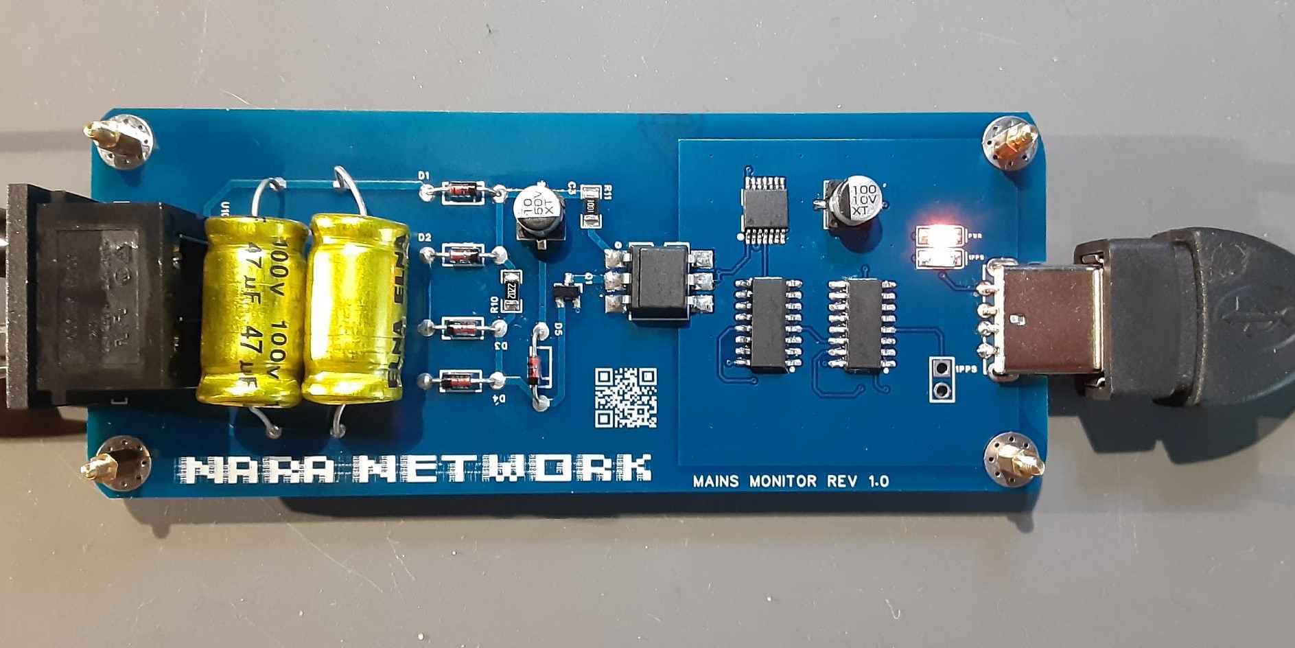
The circuit for capturing the frequency and phase is
relatively simple : A down-step transformer reduce the voltage
to 9VAC then arrives to a zero cross
circuit (transistor based with an optocoupler) Then a schmitt
trigger pass the signal in the DC area to two frequency
dividers that reduces the mains
frequency detected to 1Hz , feeding the serial line of a
laptop , where the software capture and elaborate the data.
Capturing API
The software for capturing the mains frequency is a modified version of the RFC 2783 written by U. Windl. One convenient means to provide a PPS signal to a computer system is to connect that signal to a modem-control pin on a serial-line interface to the computer. The Data Carrier Detect (DCD) pin is frequently used for this purpose. Typically, the time-code output of the time source is transmitted to the computer over the same serial line. The computer detects a signal transition on the DCD pin, usually by receiving an interrupt, and records a timestamp as soon as possible.
The typical use of this facility is for the operating system to record ("capture") a high-resolution timestamp as soon as possible after it detects a PPS signal transition (usually indicated by an interrupt). This timestamp can then be made available, with less stringent delay constraints, to time-related software. The software can compare the captured timestamp to the received time-code to accurately discover the offset between the system clock and the precise time source.
Although the primary purpose of this API is for capturing true pulse-per-second events, the API may also be used for accurately timestamping events of other periods, or even aperiodic events, when these can be expressed as signal transitions. In principle, the rate of events to be captured, or the frequency of the signals, can range from once per day (or less often) to several thousand per second. However, since in most implementations the timestamping function will be implemented as a processor interrupt at a relatively high priority, it is prudent to limit the rate of such events. This may be done either by mechanisms in the hardware that generates the signals, or by the operating system.
Although the basic implementation of the code in C is set up to receive the signal of "asserts" and "clears" for pulse-per-second signals, other types can still be recorded as well: as far as it relates to 50Hz being a relatively slow speed, it is possible to successfully capture all cycles of the frequency and later process them with other programs, which extract the phase in detail for example and set up formats with timestamps to be later depicted in graphs with GNUPLOT.
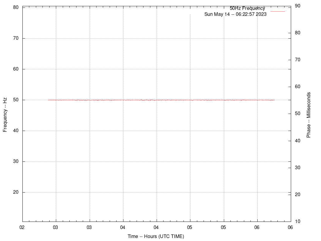
This is an example of when connecting a 9V (DB level) AC source at 50 Hz:
RFC 2783 has been slightly modified in order to have a better and clearer output from the serial line in order for a script to manipulate the data. Here is the raw output example:
assert 3430832 time 1683003744.594031762 delta 0.019984925 offset -405968238 jitter -11174
assert 3430833 time 1683003744.614030934 delta 0.019999172 offset -385969066 jitter 14247
assert 3430834 time 1683003744.634016207 delta 0.019985273 offset -365983793 jitter -13899
assert 3430835 time 1683003744.654010141 delta 0.019993934 offset -345989859 jitter 8661
assert 3430832 is the assert number. A (PPS for the purpose of this API) signal consists of a series of pulses, each with an "asserted" (logical true) phase, and a "clear" (logical false) phase. The two phases may be of different lengths. The API may capture an "assert timestamp" at the moment of the transition into the asserted phase, and a "clear timestamp" at the moment of the transition into the clear phase.
time 1683003744.594031762 is the timestamp detected with nanosecond precision, expressed in UNIX time. In the NTP protocol, "timestamps are represented as a 64-bit unsigned fixed-point number, in seconds relative to 0h on 1 January 1900. The integer part is in the first 32 bits and the fraction part in the last 32 bits. The precision of this representation is about 200 picoseconds."
delta 0.019984925 is the difference in time between the two timestamps.
offset -405968238 it is the offset around current second of the machine.
jitter -11174 jitter between event time stamps (delta of delta).
Time synchronization
In order to keep the laptop clock synchronized with a reliable time source such as a GPS or an Atomic clock thus being able to measure each power line cycle, Chrony has been used instead of the classic NTP, because it is faster than NTPD and uses a better algorithm for keeping the local clock as possible accurate to the source.
Chrony performs well in a wide range of conditions, including intermittent network connections, heavily congested networks, changing temperatures (ordinary computer clocks are sensitive to temperature), and systems that do not run continuously, or run on a virtual machine. Typical accuracy between two machines synchronized over the Internet is within a few milliseconds, and for machines on a LAN within tens of microseconds. Hardware timestamping or a hardware reference clock may improve accuracy between two machines synchronized to a sub-microsecond level.
A typical output from Chronyd is the following:
Reference ID     : 179C519B (v172-105-221-80.ntp.tyo2l.rnode.jp)
Stratum          : 4
Ref time (UTC)   : Tue May 02 08:51:02 2023
System time      : 0.000000048 seconds fast of NTP time
Last offset      : -0.002801925 seconds
RMS offset       : 0.010625760 seconds
Frequency        : 24.133 ppm slow
Residual freq    : -0.591 ppm
Skew             : 10.939 ppm
Root delay       : 0.026025012 seconds
Root dispersion  : 0.004074866 seconds
Update interval  : 64.2 seconds
Leap status      : Normal
Which is more than enough to measure a low speed frequency such as 50/60 Hz.
Differences Between NTPD and chronyd
Things chronyd can do better than ntpd:
- chronyd can work well in an environment where access to the time reference is intermittent, whereas ntpd needs regular polling of time reference to work well.
- chronyd can perform well even when the network is congested for longer periods of time.
- chronyd can usually synchronize the clock faster and with better accuracy.
- chronyd quickly adapts to sudden changes in the rate of the clock, for example, due to changes in the temperature of the crystal oscillator, whereas ntpd may need a long time to settle down again.
- In the default configuration, chronyd never steps the time after the clock has been synchronized at system start, in order not to upset other running programs. ntpd can be configured to never step the time too, but it has to use a different means of adjusting the clock, which has some disadvantages including negative effect on accuracy of the clock.
- chronyd can adjust the rate of the clock on a Linux system in a larger range, which allows it to operate even on machines with a broken or unstable clock. For example, on some virtual machines.
- chronyd is smaller, it uses less memory and it wakes up the CPU only when necessary, which is better for power saving.
Developing Frequency and phase from the timestamps is not complicated. Here has been used a series of scripts, in Python for transformation and in BASH for system integration and upload to the webserver.
Using Numpy, Pandas and Allantools has been written a program (original version was created by myself in 2016 check the source) to extract the frequency from the timestamps series:
1683024301.930496255
1683024301.950496125
1683024301.970494527
1683024301.990498168
1683024302.010481345
to the final result:
49.95048
49.99995
49.99578
50.00889
49.95823
50.04406
49.95823
50.00293
The program can do the same for the phase, which is a bit more complicated to extract precisely, extracting it from the frequency above:
9.363841078166225407e-02
9.435858739256458572e-02
5.752876400347094882e-02
5.467894061437698905e-02
5.360911722527959139e-02
5.253929383618219373e-02
1.034947044708541680e-02
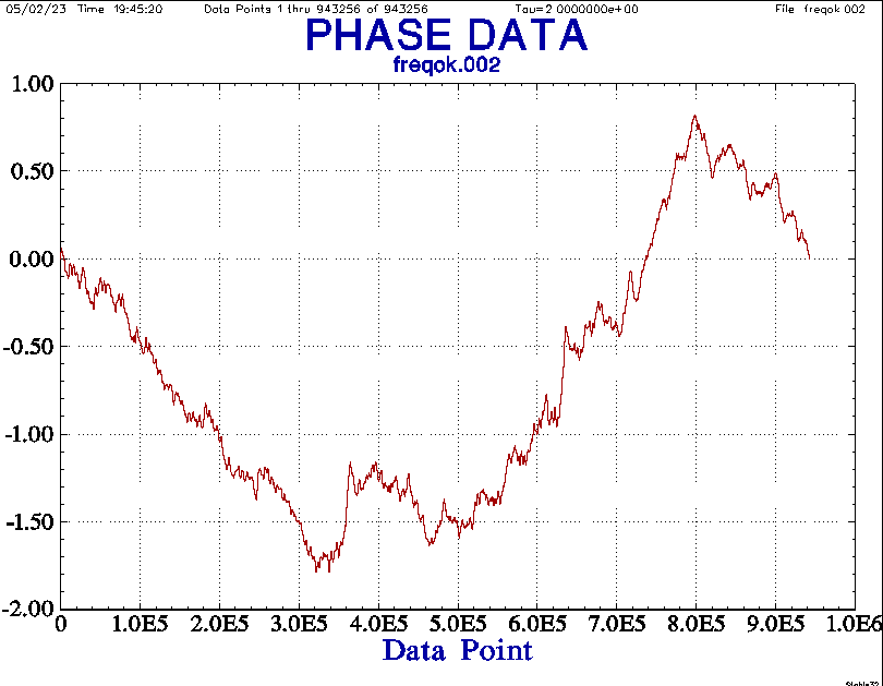
To have a comparison in precision, the same frequency output has been tried inside Stable32, one of the most famous software for time/frequency measurements. There, the phase has been extracted and compared to the same one from the python program written. Just to be sure the data result is the same (and correct):
Data Normalization and capturing techniques
The result of capturing the 50Hz/60Hz without a proper filter from the amplitude modulated signals and noise has devastating effects on the measured phase in terms of time-shift. This is an example of connecting the 9vAC transformer directly to the serial line and capturing it as-it-is:
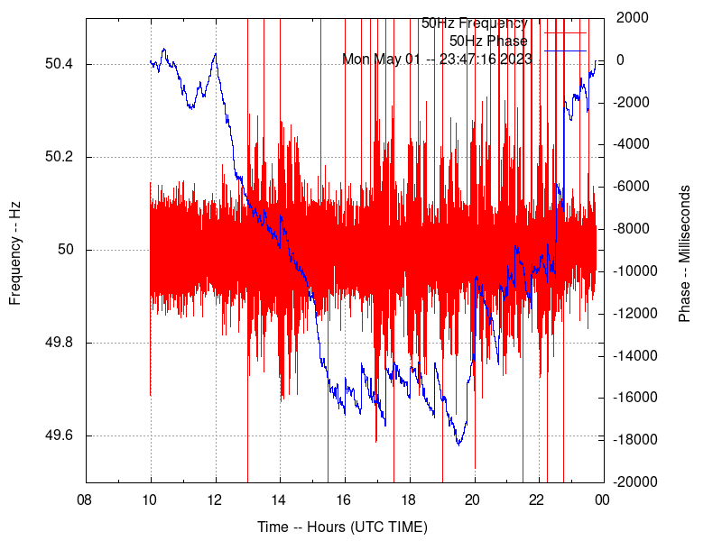
It's evident that the phase is totally shifted out, with 18 seconds (!) delay due to the noise in the mains captured as well! Not only glitches, but also amplitude modulated signals from mains noise are creating problems in measurements.
As stated also in the book The Art of Electronics by Paul Horowitz and Winfield Hill referring to PLLs and using them with 60Hz mains frequency:
In practice, that might not be the best choice for a PLL locked to the 60 Hz powerline because of the relatively high noise level present on the 60 Hz signal: many engineers have stumbled on this point, with a noisy reference signal causing false type-II triggering. With careful design of the analog input circuit (e.g., a lowpass filter followed by a Schmitt trigger) the type-II phase detector would likely perform satisfactorily; otherwise an exclusive-OR (type I) phase detector should be used.
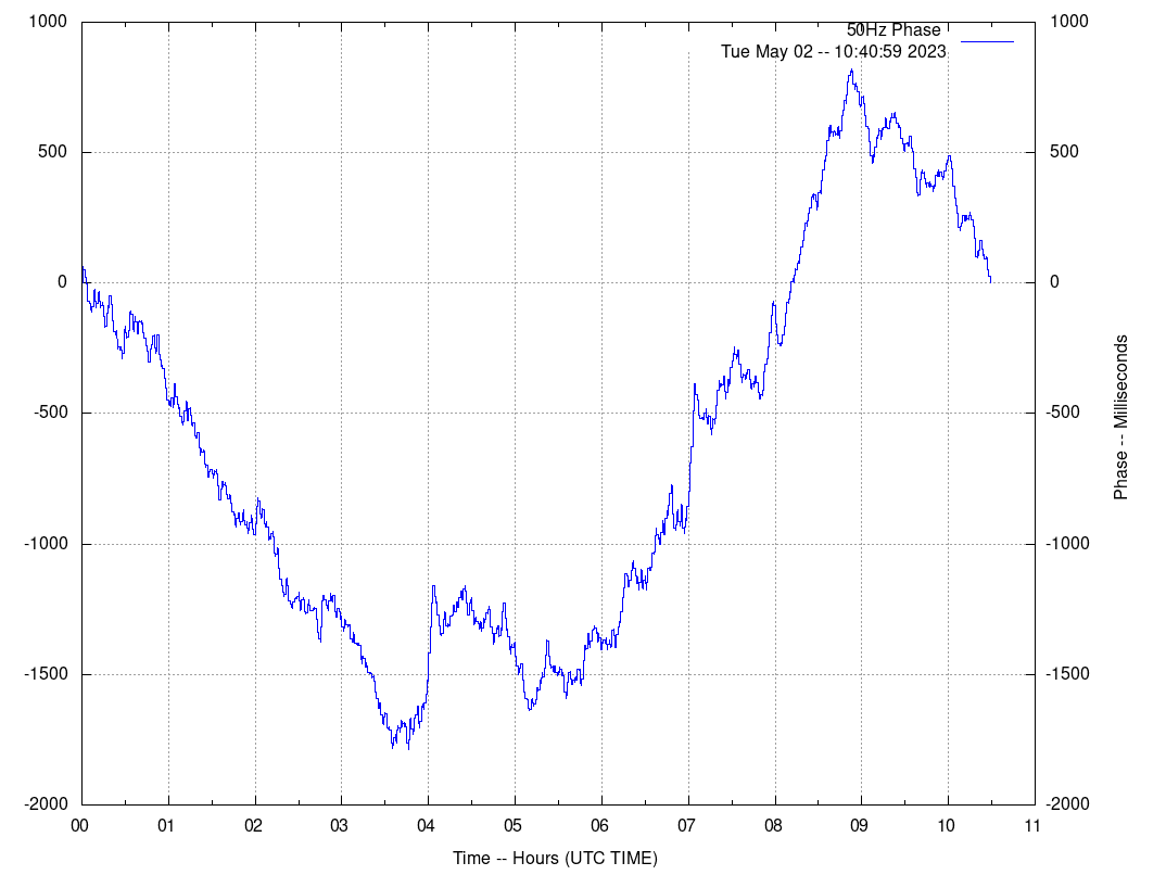
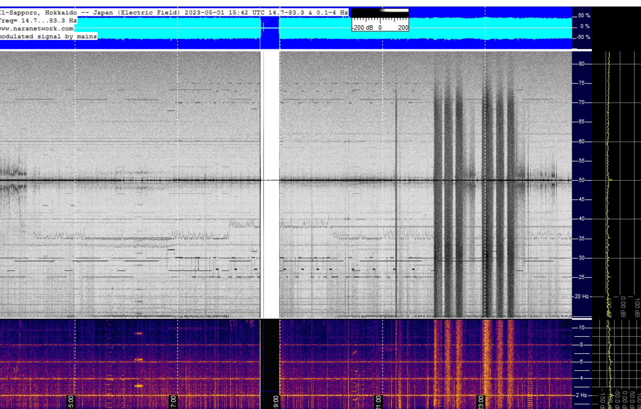
Here is another example of the modulated signals captured by the device as using 50Hz (time in the first spectrogram are JST, not UTC):
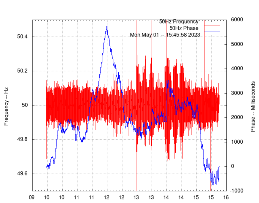
 From time to
time, it is possible to have minor glitches , much more if mains
are very disturbed by local appliances.
From time to
time, it is possible to have minor glitches , much more if mains
are very disturbed by local appliances.To avoid them a forwards-backwards exponential weighted moving average (FBEWMA) algorithm has been used , written in python.
In this way data normalization is more natural, filling eventually small gaps due to some glitches improved dramatically using this technique.
after FBEWMA:
--Update-- 01/27/2025
From a preliminary analysis of the frequency/phase data graphs, it's interesting to note few considerations in regarding of the power grid data monitored and also from the system response:
This GIF showing about three months of data (3.36 MB)
The frequency is the reciprocal of the period. However, if you look at the course of the mains voltage in a power grid, you will see many other components in addition to the fundamental frequency, such as harmonics, sub-harmonic waves, phase jumps and voltage fluctuations, which are generated by the large number of connected feeders and consumers. The mains frequency is therefore not a frequency in the physical sense, but a sum of various rotating vectors. This must be taken into account, especially in the case of dynamic processes in the power grid, in order to avoid incorrect measurement results.
Load flow calculations are carried out in advance when the power generators submit their schedules and also during network operation in order to identify critical situations and, if necessary, change the load flow through redispatching
In regarding the NNJ system, first of all, the FBEWMA is really working well as expected, preserving those spikes which are NOT related to any tiny glitches (99% of them are already removed by the initial filter and the schmitt trigger ). These spikes You see regularly for example at 14:00 time in the animated GIF ,consistently showing almost every day, are most probably related to time scheduled generators activating or deactivating during daily routine to maintain the frequency constant over casual loads on the network.
It is also possible to appreciate the scheduled (and most probably automated) frequency rise/fall (and subsequently the phase too) to keep the grid in line as much possible with time deviation that may occur.